
All articlessolar panel inspection
Solar Panel Inspection Documentation: What to Record
Inspectra AI Team October 10, 2026 9 min read
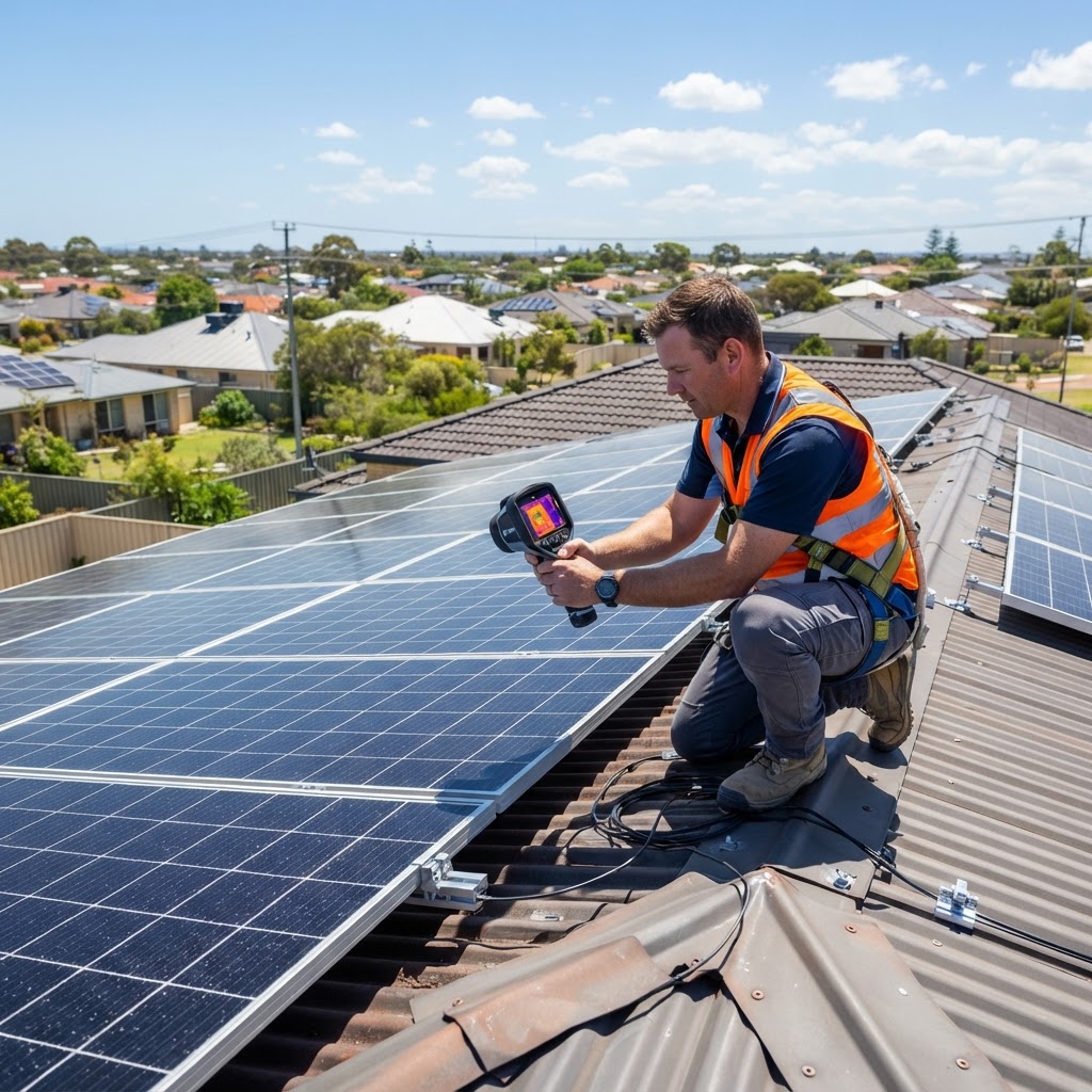
Poor solar panel inspection documentation is one of the most common reasons reports get disputed, warranties get voided, and liability falls back on the inspector. Knowing what to photograph, measure, and record — and in what order — is what separates a defensible inspection report from a liability risk.
Solar photovoltaic (PV) systems involve electrical, structural, and thermal components across multiple access zones — rooftop arrays, inverters, switchboards, and cabling runs. Most inspection failures don't happen because the inspector missed a defect. They happen because the defect wasn't recorded with enough supporting data to act on.
Common documentation gaps include:
The sections below walk through each component of a complete documentation package.
Before you climb onto a roof or open an inverter enclosure, you need a baseline record of the system as-installed.
Record the system's nameplate capacity (total installed Wp) and the inverter's AC output rating. A mismatch between these — known as the DC:AC ratio or clipping ratio — is relevant when assessing whether underperformance is a design issue or a fault.
The array is the most time-consuming part of any solar inspection. A structured approach prevents panels from being missed or double-counted.
Create or obtain a roof plan showing panel layout before you go up. Number panels in a logical sequence (e.g. left-to-right, row by row) and use that numbering in all photo filenames and field notes. Without this, a photo of delamination on "panel 14" is meaningless if you can't locate panel 14 on the array.
| Defect type | What to record | Relevant standard | |---|---|---| | Micro-cracks | Panel number, crack orientation, estimated length | IEC 61215 | | Delamination | Panel number, affected area as % of panel surface | IEC 61215 | | Soiling/shading | Source (tree, HVAC, bird droppings), affected string | IEC 62446-1 | | Discolouration / browning | Location (cell, busbar, edge) | IEC 61215 | | Frame corrosion | Severity (surface / structural), mounting point proximity | AS/NZS 5033 | | Broken glass | Panel number, crack pattern (star, linear) | Safety flag — immediate | | Bypass diode hotspots | Panel number, thermal image reference | IEC 62446-3 |
For each visual defect, capture at minimum: one wide-context photo showing the panel's position in the array, and one close-up photo showing the defect detail. Both images should have EXIF timestamp and GPS data intact — do not screenshot photos from a phone camera app, as this strips metadata.
Document rail type (flush-mount, tilt frame, ballasted), fixing method, rail-to-rafter or roof-penetration details, and any visible corrosion, movement, or inadequate clearance. In bushfire-prone zones (Australia BAL ratings), note whether the mounting system meets the relevant BAL construction requirements under AS 3959.
Visual inspection alone cannot confirm whether a system is performing to specification. String-level electrical measurements are essential and are required under IEC 62446-1 for any commissioning or periodic inspection.
Always record ambient temperature, module backsheet temperature (via contact thermometer or thermal camera), and irradiance at time of measurement using a calibrated reference cell or irradiance meter. Without these, electrical readings cannot be normalised to STC (Standard Test Conditions: 1000 W/m², 25°C cell temperature, AM 1.5 spectrum) and comparisons to nameplate ratings are invalid.
At the inverter:
At the main switchboard, document the PV AC isolator, any dedicated PV circuit breaker rating, and RCD type and rating. In Australia, the switchboard label required under AS/NZS 3000 and AS/NZS 5033 must be present and legible — photograph it.
Thermographic inspection (infrared scanning) identifies hotspots caused by cell defects, bypass diode failures, partial shading, and soiling. It is covered under IEC 62446-3 for PV-specific thermal inspection.
For each thermal anomaly, record:
A ΔT of 10–20°C typically indicates a moderate defect; ΔT above 20°C is generally classified as a serious fault requiring priority remediation. These thresholds align with IEC 62446-3 and are widely referenced in CEC and MCS guidance.
Cabling defects are a leading cause of PV system fires. Document:
Photograph every penetration point. If access beneath the array is limited, note this explicitly in the report as an inspection limitation.
Raw field data is not a report. A defensible inspection report requires:
Platforms like Inspectra AI allow inspectors to capture structured field data — photos, voice notes, measurements — and generate a formatted, professional report that meets these requirements without manual reformatting. This is particularly useful for high-volume inspectors managing multiple sites per day.
The primary standards are AS/NZS 5033 (installation and safety of PV arrays) and IEC 62446-1 (commissioning and periodic test documentation). The Clean Energy Council also publishes inspection guidelines for accredited installers and inspectors.
Most manufacturers and insurers recommend a full inspection every 2–5 years, with annual visual checks. In commercial or strata settings, many bodies corporate require annual inspection as part of common property maintenance obligations.
For any inspection that involves electrical testing (Voc, Isc, insulation resistance), yes — in Australia, the UK, and most US states, this work must be performed by or under the supervision of a licensed or registered electrician. Visual-only inspections may be conducted by other qualified tradespeople depending on jurisdiction.
IEC 62446-3 specifies a minimum of 600 W/m², though 800 W/m² or above produces more reliable results. Thermal images taken below this threshold may miss genuine hotspots or produce false positives and should not form the basis of defect classifications.
Document all access limitations explicitly in the report scope section. State which panels or sections were not inspected and why. This protects you professionally and alerts the client to gaps that may need follow-up via drone thermography or additional access provisions.
ΔT (delta T) is the temperature difference in degrees Celsius between a hotspot on a panel and an adjacent reference cell operating under the same conditions. It is the primary metric for classifying hotspot severity under IEC 62446-3.
Solar panel inspection documentation is a technical discipline with real standards behind it — IEC 62446-1, IEC 62446-3, AS/NZS 5033, MCS 012. Inspectors who record system identification, string electrical measurements, thermal imaging conditions, and structured defect classifications produce reports that hold up under scrutiny from insurers, strata managers, and asset owners.
If your current field-to-report workflow is costing you time or producing inconsistent outputs, start a free trial with Inspectra AI to see how structured capture and AI-assisted drafting can improve both speed and report quality.